5G wireless bearer under EN-DC architecture
In the initial stage of 5G deployment, in order to save costs and quickly develop services, most operators choose the non-independent networking (NSA) mode. Due to the cost and maturity of the 5G core network, 5G base stations in the NSA mode preferentially access the 4G core network (EPC). Therefore, the Option 3 series (Option 3x) is the first choice for introducing eMBB services in the early stage of 5G.

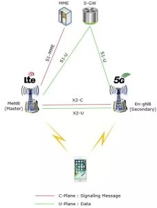
In the architecture diagram of Option 3x in the above figure, the red line represents the control plane (C-Plane), which is used to transmit control signaling. It has the following characteristics:
There is a control plane link called S1-MME between the 4G base station and the core network;
The 5G base station does not have a control plane link directly to the core network;
There is a control plane link called X2-C between the 4G base station and the 5G base station;
The 4G base station is connected to the 4G core network as a control plane anchor point and assumes all control plane functions, so it is also called a “master node.” The 5G base station does not undertake the control plane function, and its interaction with the control plane of the core network is completely dependent on 4G, so it is called a “secondary node.”
The green line in the figure represents the user plane (U-Plane), which is used to transmit user data. It has the following characteristics:
There is a user plane link called X2-U between the 4G base station and the 5G base station;
Both 4G base stations and 5G base stations have S1-U user plane links to the core network.
In summary, the option 3 series architecture is a dual connection with 4G as the primary node and 5G as the secondary node, so it is also called EN-DC (EUTRA-NR Dual Connection). In such a dual-connection architecture, mobile phones have two paths to reach the core network via 4G or 5G base stations. So, which path should the data take? There are 3 choices:
Go 4G!
Go 5G!
Aren’t we dual-connected, so both 4G and 5G are going on at the same time!
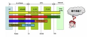
The word path mentioned above has a professional term called “bearing” in this scenario, which means the logical path that provides services to mobile phones and bears services. The length of the connection path between different network elements is different, and the corresponding bearer name is also different. So, where is the bearer mentioned here, and which two network elements are connected?

As shown in the figure above, since we are concerned with how 4G and 5G distribute data to mobile phones (UE) over the air interface, the bearer here specifically refers to the radio bearer between the mobile phone and the 4G/5G base station.
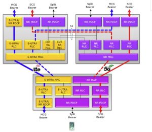
In general, the 4G base station as the master node uses multiple different frequency points to form a network of multi-layer cells. These cells can be used as control plane anchor points. Therefore, these 4G cells are collectively referred to as the master cell group (MCG: Master Cell Group). Group), the wireless data bearer established on it is called MCG bearer, which corresponds to Option 1: Only use the 4G path.
Correspondingly, multiple 5G cells form a secondary cell group (SCG: Secondary Cell Group), and the wireless data bearer established on it is called the SCG bearer, which corresponds to Option 2: Take the 5G path.
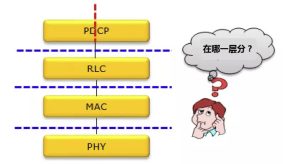
For option 3, MCG and SCG are required to cooperate to split the air interface data into two bearers, so it is called Split Bearer. So where did this “bearer” “split”?
First, let’s look at the air interface protocol stack. 5G and 4G are similar, and both include the processing of the PDCP, RLC, MAC, and PHY layers. The “split” and “convergence” of the split bearer are handled by the PDCP layer.

Downlink data starts from the PDCP layer and is sent to the RLC/MAC/PHY layers of 4G and 5G for independent processing. Finally, the mobile phone receives both 4G and 5G data at the same time. The same applies to the uplink, but in the opposite direction. Two channels of data are sent from the mobile phone to the 4G and 5G base stations, and then processed by their respective PHY/MAC/RLC layers, and finally merged at the PDCP layer.

As shown in the figure above, for MCG bearers, regardless of whether the PDCP layer is 4G (E-UTRA) or 5G (NR), it will be transferred to the RLC/MAC/PHY layer of the 4G base station for processing, which means that the MCG bearer is based on 4G; Correspondingly, for the SCG bearer, the entire PDCP/RLC/MAC/PHY is processed by the 5G module, which means that the SCG bearer is based on 5G; Finally, for the split bearer, the data is split into two paths from the PDCP layer of 5G NR, and then to the RLC/MAC/PHY layer of 4G and 5G for processing.

